Links
INSTALLATION METHODOLOGY TURBINES
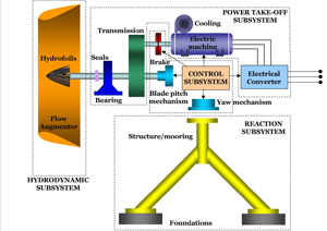
| There are three major sub-assemblies of a tidal turbine: |
The hydrodynamic sub-system (or rotor) when linked with the power take off system forms the “drive train” which is unique to each device manufacturer. However, the foundation or drive train support structure can vary considerably between manufacturers as can the method of securing it in location. Foundations can be piled, or drilled and pinned (pin piled), or simply held in place by massive gravity base structures. The foundation or support structure can be subsurface surface penetrating, or even moored depending on site and seabed conditions and installation and operation costs.
The two example machines used for the Environmental Impact Assessment, the Siemens MCT SeaGen S and Alstom TGL device (ex RollsRoyce), currently use a sea bed fixed pin-piled foundation with three or four pins as illustrated below.
The two example machines used for the Environmental Impact Assessment, the Siemens MCT SeaGen S and Alstom TGL device (ex RollsRoyce), currently use a sea bed fixed pin-piled foundation with three or four pins as illustrated below.
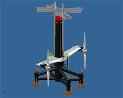 Siemens MCT SeaGen S with Quadrapod |
 Alstom TGL with Tripod |
|---|
Installation of these types of foundation requires subsea drilling and therefore a vessel which can hold station by using anchors, Dynamic Positioning, or by a combination of these utilising a jack up barge with legs which locate the vessel stationary relative to the seabed before commencing deployment of the drill. |
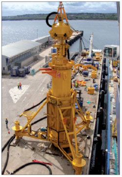 Bauer Subsea Drill |
|---|
Each of these vessel types have their own advantages depending on the site conditions – wind and waves, tidal flows, seabed conditions, and depth etc and this needs to be factored into the installation methodology as well as the impact on technology choice (e.g. weights and component sizes) and vessel availability.
Dynamic Positioning (DP) systems utilise computer control of pushers and propellers to enable vessel to hold position independent of anchors and other support system.
Jack up vessels are positioned either by use of anchors or DP thrusters and then lifted out of the sea to undertake works. DEME’s innovation is a DP Jack Up Barge
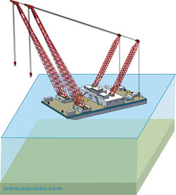 Crane Barge Positioned with Anchors |
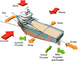 DP Ship Controlled by Thrusters |
|---|
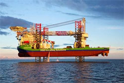 DEME’s DP Jack Up Vessel – The Innovation |
|---|
One of the biggest challenges associated with the development of Tidal Energy is the high installation and maintenance costs. One solution to reduce these costs is to provide an alternative moored surface support structure. One example of this is the Bluepower BlueTEC device illustrated below. These structures require smaller installation vessels which are one the major costs; they also allow dry cable connections and easy access for maintenance utilising smaller more local boats.
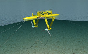 BlueTEC Moored Device with Siemens Turbines - Installed |
|---|
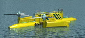 BlueTEC Moored Device with Siemens Turbines - Maintenance |
INSTALLATION METHODOLOGY – SUBSEA CABLE
Both turbine inter-array cables and the main export cable are likely to be installed by the same methodology from a specialised cable laying vessel.
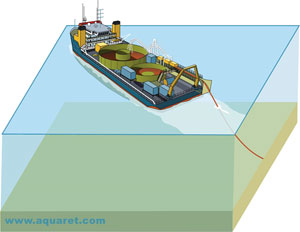 Specialist Cable Laying Vessel |
|---|
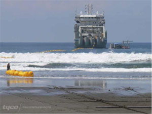 Specialist Cable Laying Vessel making landfall |
Laying subsea cable is in itself not a new technique and there are many submarine cables for telecommunications and electricity. However, the challenges in this instance are laying cables in a high tidal energy environment and subsequently protecting the cable from potential damage due to that environment. Careful cable routing utilising natural seabed features can help keep the armoured cable out of the most aggressive tidal flows until the cable run reaches lower velocity areas.
Once in areas with lower tidal movement, and seabed sediment it is normal that the cable would self bury over time under its own weight. In the high tidal areas where there is high energy and rock seabed, beyond the routing through natural features special techniques may also be required to protect the cable.
Inter-array cables (connecting between the individual turbines) will be installed directly onto the rock seabed and configured to utilise localised fissures where possible and to be laid in parallel to the tidal flow where this is not possible. Where necessary, the cables will also be weighted down by the use of cable protectors, concrete mattresses or rock bags.
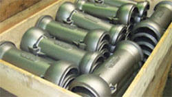 Cast Iron Cable Protectors |
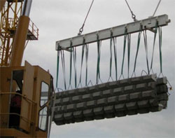 Concrete Mattresses being Deployed |
|---|---|
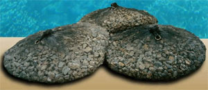 Rock Bags in Situ |
|
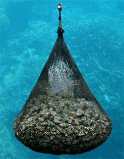 Rock Bag Being Lowered |
|
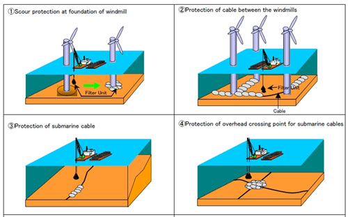 Different Applications for Rock Bag Installation |
|
Where the export cable reaches landfall the technique for making landfall depends on the shoreline geography. If the landfall is rocky and steep directional drilling may be required. However, where a shelving beach is available it is possible to trench the cable at low water through the intertidal zone, and plough the cable to a suitable distance off the beach to ensure the cable is not visible and safely away from human contact .
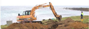 Onshore Cable Trenching |
|---|
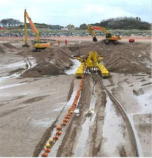 Tidal Zone Cable Plough Trenching |
In principle it is possible to complete the landfall and to restore the beach to its original condition without any remaining visual evidence of the installation.

